

Model no
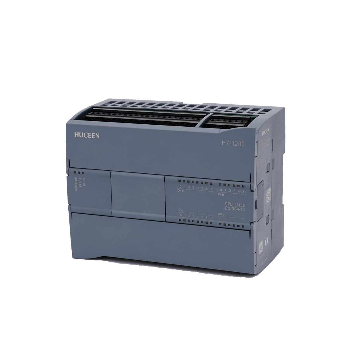
CPU 1215C DC/DC/RLYArticle No
H7 215-1HG31-0XB0Description
CPU 1215C DC/DC/RLY 14DI/10DO 2AI/2AO 2*RJ45WxHxD(mm)
130×100×75mm


| Specification parameters | Model no | CPU 1215C DC/DC/Relay |
| Article No | H7 215-1HG31-0XB0 |
| Conventional norm | Dimensions WxHxD(mm) | 130×100×75mm |
| Weight | 600 g | |
| Power Loss, Typ. | 12 W | |
| Available Current (SM and CM Bus) | Max. 1600 mA (5 VDC) | |
| Available Current (24 VDC) | Max. 400 mA (Sensor Power) | |
| Digital Input Current Consumption (24 VDC) | 4 mA per input point |
| CPU Features | 250 KB(Working) | |
| User Memory: | Built-in 4 MB(Load) | |
| 10 KB(Retention) | ||
| Onboard Digital I/O | 14 inputs / 10 outputs | |
| Onboard Analog I/O | 2 inputs / 2 outputs | |
| Process Image Size | 1024 bytes input (I) / 1024 bytes output (Q) | |
| Bit Memory (M) | 8192 bytes | |
| Temporary (Local) Memory | 16 KB for startup and program cycle (including related FBs and FCs) 8 KB for other interrupt events (including FBs and FCs) |
|
| Signal Module Expansion | Up to 8 signal modules | |
| SB, CB, BB Expansion | Up to 1 | |
| Communication Module Expansion | - | |
| High-Speed Counters | 6 total Single-phase: 3 × 100 kHz, 3 × 30 kHz Quadrature: 3 × 80 kHz, 3 × 20 kHz |
|
| Pulse Output | Not supported | |
| Pulse Capture Inputs | 14 | |
| Timed / Cyclic Interrupts | 4, with 1 ms accuracy | |
| Edge Interrupts | 12 rising edges and 12 falling edges | |
| Memory Card | Not supported | |
| Real-Time Clock Accuracy | ±60 s/month | |
| RTC Retention | Typically 20 days, minimum 12 days at 40°C (maintenance-free super capacitor) |
| Performance | Boolean Operation SpeedNote | 0.26 μs/instruction |
| Word Move Speed | 0.43 μs/instruction | |
| Floating-Point Add Speed | 1.36 μs/instruction | |
| Note : Many variables affect the measurement time. The above performance times apply to this class and the fastest instructions in an error-free program. |
| Communication | Ports | 2 |
| Type | Ethernet | |
| HMI Devices | 4 | |
| Programming Device (PG) | 1 | |
| Connections | 8 for open user communication (active or passive): TSEND_C, TRCV_C, TCON, TDISCON, TSEND, TRCV 8 for server GET/PUT (CPU-to-CPU S7 communication) 8 for client GET/PUT (CPU-to-CPU S7 communication) |
|
| Data Transfer Rate | 10/100 Mb/s | |
| Isolation (External Signal vs PLC Logic) | Transformer isolation, 1500V AC (short-term event only) | |
| Cable Type | Shielded CAT5e |
| Power Supply | Voltage Range | 20.4-28.8V DC |
| Frequency | - | |
| Input Current: | ||
| Surge Current (Max) | 500 mA CPU only (24 VDC) Max Load 1500 mA CPU with all expansions (24 VDC) Max Load |
|
| Surge Current (Max) | 12 A at 28.8 VDC | |
| Isolation (Input Power vs Logic) | None | |
| Leakage current, AC line to functional ground | - | |
| Hold Time (Power Loss) | 10 ms at 24 VDC | |
| Internal Fuse (User Non-Replaceable) | 1 A, 60 V, PTC self-resetting |
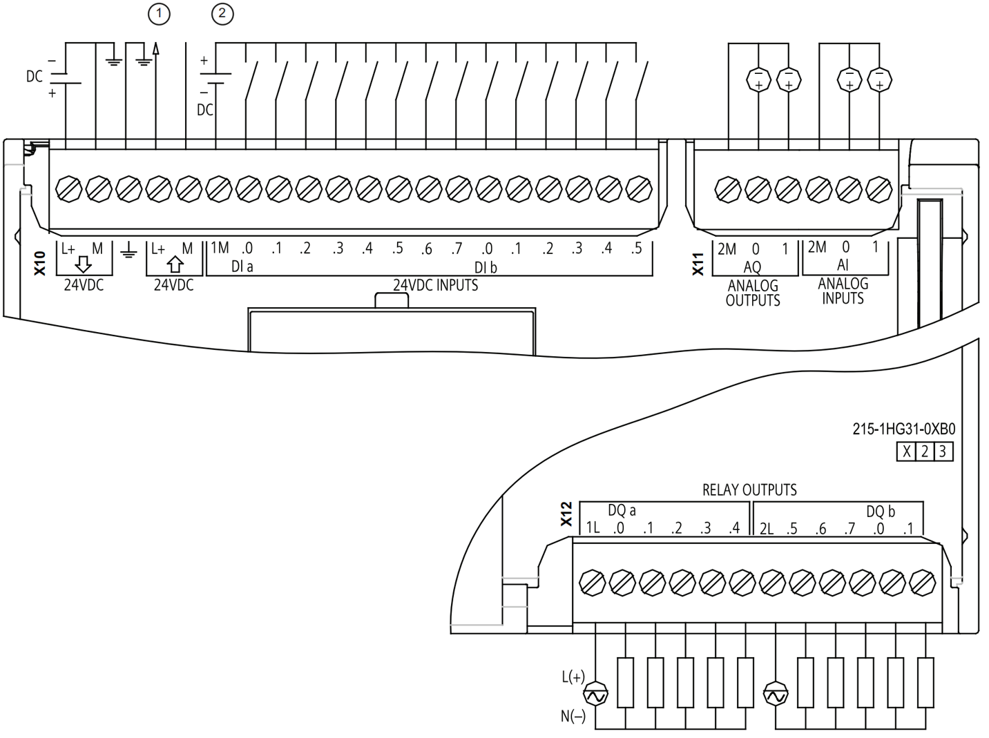
| Digital Inputs | Number of Inputs | 14 |
| Type | Sink/Source (IEC Class 1 Sink) | |
| Rated Voltage | 24 VDC at 4 mA | |
| Permissible Continuous Voltage | Max 35 VDC | |
| Surge Voltage | 60 VDC for 1 min | |
| Logic 1 Signal (Min) | 15 VDC at 2.5 mA | |
| Logic 0 Signal (Max) | 5 VDC at 1 mA | |
| Isolation (Field side vs. Logic side) | 500 VAC, 1 min continuous | |
| Isolation group | 1 | |
| Filter time | 0.2, 0.4, 0.8, 1.6, 3.2, 6.4, and 12.8 ms (selectable, 4 per group) | |
| Maximum HSC clock input frequency (Logic 1 level = 15 to 26 VDC) |
Single-phase: 100 kHz (Ia.0 to Ia.5) and 30 kHz (Ia.6 to Ib.5) Quadrature phase: 80 kHz (Ia.0 to Ia.5) and 20 kHz (Ia.6 to Ib.5) |
|
| Number of simultaneously active inputs | 14 | |
| Cable length (m) | 500 m (shielded); 300 m (unshielded); 50 m (shielded, HSC input) |
| Digital Output | Number of Outputs | 10 |
| Type | Relay, dry contact | |
| Voltage range | 5 to 30 VDC or 5 to 250 VAC | |
| Logic 1 voltage at max. current | - | |
| Logic 0 voltage with 10 kΩ load | - | |
| Current (max) | 2.0 A | |
| Lamp load | 30 W DC / 200 W AC | |
| On-state resistance | Max 0.2 Ω (new device) | |
| Leakage current per point | - | |
| Surge current | 7 A when contacts closed | |
| Overload protection | None | |
| Isolation (Field side vs. Logic side) | 1500 VAC, 1 min (coil-to-contact); None (coil-to-logic) | |
| Isolation resistance | Min 100 MΩ (new device) | |
| Insulation between contacts | 750 VAC, 1 min | |
| Isolation group | 2 | |
| Inductive clamping voltage | - | |
| Switching delay (Qa.0 to Qa.3) | Max 10 ms | |
| Switching delay (Qa.4 to Qb.1) | Max 10 ms | |
| Maximum relay switching frequency | 1 Hz | |
| Pulse train output frequency (Qa.0 and Qa.2) |
Not recommended | |
| Mechanical lifetime (no load) | 10,000,000 make/break cycles | |
| Contact lifetime at rated load | 100,000 make/break cycles | |
| RUN-to-STOP behavior | Previous value or replacement (default = 0) | |
| Number of simultaneously active outputs | 10 | |
| Cable length (m) | 500 m (shielded); 150 m (unshielded) |
| Analog Input | ||
| Number of input channels | 2 | |
| Type | Voltage (single-ended) | |
| Full-scale range | 0 to 10 V | |
| Full-scale range (digital value) | 0 to 27,648 | |
| Overshoot range | 10.001 to 11.759 V | |
| Overshoot range (digital value) | 27,649 to 32,511 | |
| Overflow range | 11.760 to 11.852 V | |
| Overflow (digital value) | 32,512 to 32,767 | |
| Resolution | 10-bit | |
| Maximum withstand voltage | 60 VDC | |
| Smoothing | None / Weak / Medium / Strong | |
| Noise suppression | 10 / 50 / 60 Hz | |
| Input impedance | ≥100 kΩ | |
| Isolation (field vs. logic) | None | |
| Accuracy (25 ºC / -20 to 60 ºC) | 0.5% / 1.0% of full scale | |
| Cable length (m) | 100 m, shielded twisted pair |
| Analog Output | ||
| Number of output channels | 2 | |
| Type | Current | |
| Range | 0 to 20 mA | |
| Full-scale range (digital value) | 0 to 27,648 | |
| Maximum voltage/current rating | 60 VDC / 40 mA | |
| Overshoot range | 20.01 to 23.52 mA | |
| Overshoot range (digital value) | 27,649 to 32,511 | |
| Overflow range | On overflow, analog output behavior follows device configuration. For the “Response to CPU STOP” parameter, choose either replacement value or hold previous value. | |
| Overflow range (digital value) | 32,512 to 32,767 | |
| Resolution | 10-bit | |
| Output driving impedance | Max 700 Ω | |
| Isolation (field vs. logic) | None | |
 +86 13713990149
 sales@huceen.com
 /5F, No.1 Building, Esun 3D Industrial Park, ZhongWu Community, HangCheng Street, BaoAn District, Shenzhen.
Copyright @ 2026 Shenzhen Huceen Automation Technology CO,LTD


 +86 13713990149
 sales@huceen.com